
Description
Frenic VG Series 3-phase 200V
- FRN0.75VG1S-2A : 0.75kW
- FRN1.5VG1S-2A : 1.5kW
- FRN2.2VG1S-2A : 2.2kW
- FRN3.7VG1S-2A : 3.7kW
- FRN5.5VG1S-2A : 5.5kW
- FRN7.5VG1S-2A : 7.5kW
- FRN11VG1S-2A : 11kW
- FRN15VG1S-2A : 15kW
- FRN18.5VG1S-2A : 18.5kW
- FRN22VG1S-2A : 22kW
- FRN30VG1S-2A : 30kW
- FRN37VG1S-2A : 37kW
- FRN45VG1S-2A : 45kW
- FRN55VG1S-2A : 55kW
- FRN75VG1S-2A : 75kW
- FRN90VG1S-2A : 90kW
Frenic VG Series 3-phase 400V
- FRN3.7VG1S-4A : 3.7kW
- FRN5.5VG1S-4A : 5.5kW
- FRN7.5VG1S-4A : 7.5kW
- FRN11VG1S-4A : 11kW
- FRN15VG1S-4A : 15kW
- FRN18.5VG1S-4A : 18.5kW
- FRN22VG1S-4A : 22kW
- FRN30VG1S-4A : 30kW
- FRN37VG1S-4A : 37kW
- FRN45VG1S-4A : 45kW
- FRN55VG1S-4A : 55kW
- FRN75VG1S-4A : 75kW
- FRN90VG1S-4A : 90kW
- FRN110VG1S-4A : 110kW
- FRN132VG1S-4A : 132kW
- FRN160VG1S-4A : 160kW
- FRN200VG1S-4A : 200kW
- FRN220VG1S-4A : 220kW
- FRN280VG1S-4A : 280kW
- FRN315VG1S-4A : 315kW
- FRN355VG1S-4A : 355kW
- FRN400VG1S-4A : 400kW
- FRN500VG1S-4A : 500kW
- FRN630VG1S-4A : 630kW
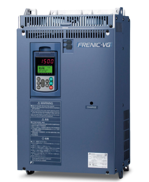
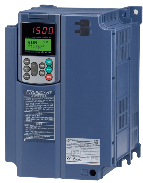
FRENIC-VG Series
- High performance enabled by the comprehensive use of Fuji technology.
- Easy maintenance for the end-user.
- Maintains safety and protects the environment.
- Opens up possibilities for the new generation.
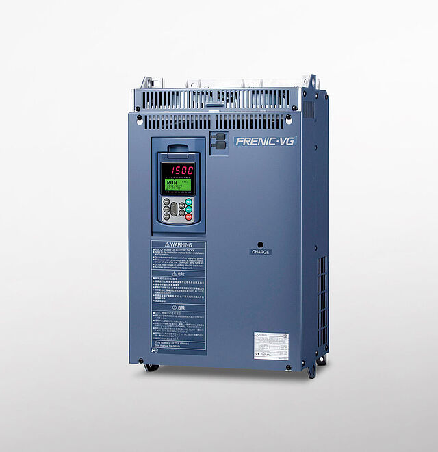
Inverter (Unit Type)
This type consists of the converter and inverter circuits.The inverter can be operated using a commercial power supply.
* DC power can also be supplied without using the converter circuit.
Structure
- Built-in converter (rectifier)
- Built-in control circuit
- External DC reactor as standard*
- DC input is available.
* Available for 75kW or higher capacity models
Features
- Easier arrangement for small-scale system
Inverter (Stack Type)
The converter and inverter sections are separately set in this type.The converter (diode stack) or PWM converter is required depending on the intended use. Moreover, a combination of inverters can be used with one converter.
Structure
- The converter (rectifier) is separately set.
- External control circuit
- Built-in DC reactor
Features
- DC supply enables the multi-drive arrangement
- Energy can be shared within DC bus lines.
- Downsized panel
- Large-capacity system is easily built.
- Maintainability
Ratings for intended use
The operation mode for the motor is selected according to motor load condition. Motors larger by one or two frames can be driven with medium load (MD) and light load (LD) use.
dasda
| Specification | Applied load | Feature | Applicable overload rating | Power supply voltage |
Applicable motor capacity [kW] | |
|---|---|---|---|---|---|---|
| Unit Type |
Stack Type*2 |
|||||
| HD | High Duty Spec | Powerful drive at low noise | Current: 150% 1min/200% 3sec | 200V | 0.75 to 90 | – |
| 400V | 3.7 to 630 | – | ||||
| MD | Middle Duty Spec | Can drive motors of frames one size larger*1 | 150% 1min | 200V | – | – |
| 400V | 110 to 450*2 | 30 to 800 | ||||
| LD | Low Duty Spec | Can drive motors of frames one or two sizes larger*1 | Unit type:120% 1min Stack type:110% 1min |
200V | 37 to 110 | – |
| 400V | 37 to 110 | 37 to 1000 | ||||
Note) A DCL may be selected according to applicable specifications.
*1 This varies depending on motor specifications and power supply voltage (unit type only).
*2 Carrier frequency becomes 2kHz.
A standard built-in brake circuit with expanded capacity range
Having a standard built-in brake circuit (with 200V 55kW or less and 400V 160KW or less), is useful when applying the inverter to the vertical transfer machine, which is frequently used under the regenerative load.
* Unit type only
Servo function
Position control by built-in APC
The ABS encoder I/F option card with 17-bit high resolution has been prepared.
Pulse train input enabled (optional)
The option card for the SX and E-SX bus I/F has been prepared.
Control method
Not only the induction motors but also the synchronous motors can be driven, and for the induction motors, you can select the most suitable control method according to your individual needs.
| Target motors | Control method |
|---|---|
| Induction motor |
|
| Synchronous motor |
|
A wide range of options
- Providing options supporting various interfaces such as high-speed serial communications
- Options can be used by just inserting them into the connectors inside the inverter. Up to five cards can be mounted. (For details, please contact us because the combination of the optional cards has some restrictions.)
| Categoly | Name | Type | |
|---|---|---|---|
| Analog card | Synchronized interface | OPC-VG1-SN*1 | |
| F/V converter | OPC-VG1-FV*1 | ||
| Analog input/output interface expansion card | OPC-VG1-AIO | ||
| Digital card (for 8-bit bus) | Digital input | OPC-VG1-DI | |
| Digital input | OPC-VG1-DIO | ||
| PG interface card | +5V line driver | OPC-VG1-PG | |
| Open collector | OPC-VG1-PGo | ||
| ABS encoder with 17-bit high resolution | OPC-VG1-SPGT | ||
| PG card for synchronous motor drive | Line driver | OPC-VG1-PMPG | |
| Open collector | OPC-VG1-PMPGo | ||
| T-Link communication card | OPC-VG1-TL | ||
| CC-Link communication card | OPC-VG1-CCL | ||
| High-speed serial communication card (for UPAC) | OPC-VG1-SIU*1 | ||
| Digital card (for 16-bit bus) | SX bus communication card | OPC-VG1-SX | |
| E-SX bus communication card | OPC-VG1-ESX | ||
| User programming card | OPC-VG1-UPAC*1 | ||
| PROFINET-IRT communication card | OPC-VG1-PNET*1 | ||
| Safety card | Functional safety card | OPC-VG1-SAFE | |
| Field bus interface card | PROFIBUS-DP communication card | OPC-VG1-PDP*1 | |
| DeviceNet communication card | OPC-VG1-DEV*1 | ||
| Control circuit terminal | Terminal block for high-speed communications | OPC-VG1-TBSI | |
Standard specifications
HD specification for heavy overload (Unit Type)
Three-phase 200V series

Three-phase 400V series

Features
- Powerful: from 0.75 kW to 630 kW in triple rating HD, LD and MD
- Robust: can also be used in problematic environments, for example under sulphurous gases, salty atmospheres, dust, humidity, etc.
- Flexible: IM control (open and closed loop) and PMSM control (open and closed loop)
- Torque accuracy: +/- 3 %
- Current loop bandwidth: 2000 Hz
- Speed control accuracy: +/- 0,005 %
- Speed loop bandwidth: 600 Hz
- Connections: USB on board, typical field buses and Ethernet-based field bus
- Safety – made simple: STO, SS1, SLS, SBC
- Solutions for all applications: Cranes, rubber, paper, winding, test benches, presses, marine winches, flying saw systems, positioning, etc.
- Versatile and customizable: 5 slots to adapt to requirements, integrated real-time clock, FULL PLC on board, etc.